| |
|
Description
The
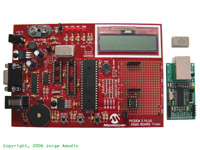
PICDEM 2 PLUS board is a simple board from Microchip Technology to demonstrate
the capabilities of several of Microchip's 8-bit Microcontrollers.
The board includes 18, 28 and 40-pin IC sockets, a 24LC256 Serial EEPROM,
a TC74 temperature sensor, a 16x2 character LCD module, a RS232 serial
interface, etc.
This project will show you how to add a network interface card based on the
ENC28J60 Standalone Ethernet Controller to the PICDEM 2 PLUS and how to get
it up and running on a network using Microchip's free TCP/IP stack software.
|
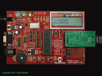
PICDEM 2 Plus
[Click Image to Enlarge]
|
Design considerations
PICDEM 2 PLUS modifications
The PICDEM 2 PLUS includes a 24LC256 Serial EEPROM, and a TC74 temperature sensor,
both devices use the I2C interface that is implemented using the MSSP
module of the microcontroller, the ENC28J60 uses the SPI interface that
is implemented using the same MSSP and it can not be configured to run
as I2C and SPI at the same time. Then to be able to interface with the
ENC28J60 and avoid pin sharing conflicts it's necessary to isolate these
two devices.
Instead of removing them from the board this can be achieved by cutting few
traces and adding few wires, I'll show you what traces to cut later.
Microcontroller selection & external memory
The PICDEM 2 PLUS ships with a PIC16F877A and a PIC18F452. The Microchip
TCP/IP stack does not support any of the PIC16 family controllers, but
you can still write your own code to interface with the ENC28J60 if you wish.
You can squeeze the TCP/IP stack image on the PIC18F452 but a better option due
it's additional program and RAM memory space is the PIC18F4620 or the PIC18F2620
if fewer I/O interfaces are needed. Both PICs will work with the PICDEM 2 PLUS,
but with the PIC18F2620 you will not be able to interface with the LCD included
on the board.
I tested this project with several microcontrollers including the PIC18F452,
PIC18F4520, PIC18F2520, PIC18F2525, PIC18F4525, PIC18F4620 and PIC18F2620.
To maximize program memory space (and be able to fit the code in a PIC18F452)
I added an external 25LC256 Serial EEPROM. The 25LC26 is very similar to the
24LC256, among of the main differences are that the 25LC256 uses the SPI interface
that can be shared with the ENC28J60 and the device much faster than the I2C part
(the latest version of the modified TCP/IP stack also supports the new 25LC1024
Serial EEPROM with obviously four times more capacity than the 25LC256).
To select which device is active on the SPI interface we'll use the RB3 I/O
pin for the ENC28J60 CS (Chip Select) and RB4 for the 25LC256.
ENC28J60 Network Board
As you noticed the PICDEM 2 PLUS has limited prototyping space to fit all
the required components for the ENC28J60, RJ45 jack, etc. For this particular
project I used the nic28 network board
from LJCV Electronics. This board has a
small footprint (1.3x2.5") and includes a 3.3V voltage regulator and level
translation logic.
There are other boards you can use such as Microchip's
PICTail Ethernet Board, or Olimex's
ENC28J60-H, but keep in mind that the ENC28J60 has 3.3V Vdd supply and the PICDEM
2 Plus is a 5V board, then with some alternatives you will need to add a 3.3V regulator
and level translation logic to interface with the ENC28J60.
Microcontroller Clock Frequency
The ENC28J60 due a bug in silicon Revisions B1 and B4 requires a SPI clock (SCK) of at
least 8MHz, being 10MHz the maximum. This problem has been fixed in the B5 silicon revision
where the acceptable range for SCK is from DC to 20MHz.
A workaround for the B1/B4 clock synchronization problem is to use the same clock
source for the ENC28J60 and the Microcontroller, for example by using the clock
signal provided by the ENC28J60 on the CLKOUT pin. By default CLKOUT output is 6.25MHz
(25MHz/4).
To achieve better performance running the TCP/IP stack, we'll configure the
Microcontroller to use the HSPLL oscillator mode, then internally the Microcontroller
will be running at 4X the Oscillator frequency.
Keep in mind that the maximum configurable clock speed for SCK is Fosc/4, then SCK will
be equal to the Microcontroller oscillator frequency.
The PICDEM 2 Plus ships with a 4MHz TTL can oscillator, with this oscillator and
HSPLL enabled the Microcontroller will run at 16MHz and SCK will be 4MHz, unless
the ethernet board has a revision B5 ENC28J60 you will be running the ENC out
of spec and communication with it via the SPI interface will be unreliable.
The easiest alternative is just to remove the 4MHz oscillator and connect
CLKOUT from the ENC28J60 to OSC1 on the Microcontroller.
For better performance (as shown in the pictures) replace the 4MHz oscillator
by a 10MHz one, or install a 10MHz crystal and associated load capacitors
on the pads provided in the PICDEM 2 Plus (if you do so remember to remove
the can oscillator from its socket).
Schematics
There is not much that we can draw in terms of schematics, but here is
a simple one showing how we will connect the different parts. Notice that
the diagram includes an optional connection in case you decide to use
the CLKOUT signal as the clock source for the Microcontroller.
|
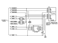
[Click on the image for a larger view]
|
Putting the Hardware together
Take in account that there are several revisions of the PICDEM 2 Plus board, the one
I used is marked "Rev 5", in the latest PICDEM 2 Plus User's Guide Microchip shows
a new board revision where several components are now surface mounted and the board
layout is a little bit different.
The schematics and options are basically the same but you may have to adapt these
instructions to your particular situation.
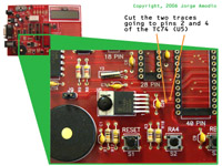
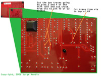
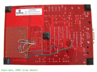
As mentioned before to isolate the 24LC256 and TC74 we need to cut few traces on the
board, two on the top side and four in the bottom side. The following two pictures
show where to perform these cuts.
|
[Click on the images for a larger view]
|
To connect the different parts I used wirewrap solid wire, to mount the 25LC256
Serial EEPROM a 8-pin IC socket, to mount the nic28 board two pairs of .1"
female and male headers, and to keep the original functionality of the PICDEM
2 Plus with the TC74 and 24LC256 a 2x2 jumper header.
In the following two pictures you will see the parts mounted on the prototype
area and the wiring on the bottom of the board.
|
[Click on the images for a larger view]
|
And the following picture shows the final product with all parts installed in place
and up and running.
|
[Click Image to Enlarge]
|
To restore the original functionality of the PICDEM 2 Plus, just remove the nic28
board and the 25LC256, and place two shunt jumpers on the 2x2 headers to reconnect
the TC74 and 24LC256 to the I2C interface pins.
If you have or are planning to buy a PICDEM 2 Plus board and want to venture with
this project I made all the required parts available as a kit through
LJCV Electronics, the kit includes a PIC18F4620
Microcontroller, a 25LC256 Serial EEPROM, a 8-pin dip socket, a 10MHz TTL can
oscillator, the male and female headers and the 2x2 header with jumpers.
If you don't have a PICDEM 2 Plus, don't worry you can put together a similar design
using the nic28 on a solderless prototype board, here is a page
showing how to put this project together.
|
Getting the board up and running
Compiling the firmware is not a huge or complicated task, it requires few
software tools available for download from Microchip's
website at no cost, and obviously the TCP/IP stack source code distribution and a
PIC programmer. For this project I used Microchip's
MPLAB ICD2 as a programmer.
With the latest modified version of the
Microchip TCP/IP Stack v3.75, the process is quite simple.
This new version adds the PICDEM2 macro definition that
combined with the device selection for the Microcontroller generates the appropriate
code for this particular project.
The software distribution includes the MPLAB IDE project file
PICDEM2.mcp, load this project into MPLAB IDE,
select the correct processor (by default the project has selected the PIC18F4620)
and verify that the settings on the config.h and
picdem2.h files apply to your project or modify them
accordingly (both files are located in the include
subdirectory of the main src directory).
For additional details check the README.TXT file
included in the software distribution.
For a detailed explanation about how to build Microchip's TCP/IP stack
for this or similar projects Click Here.
|
Datasheets for relevant parts used in this project
Useful Links
TCP/IP Stack Source code and useful software tools
Additional Resources
|
|
|