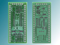
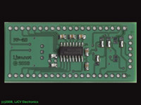
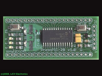
We obviously start with a new ProtoPIC28 bare PCB
|

We start on the bottom side by applying a small amount of solder
on one of the pads for each component. In this case we will populate
all the ceramic capacitors for the RS-232 transceiver and the load
capacitors for the 32KHz crystal.
|

Use the tweezers to hold the component in place while with the other hand
you place the solder iron tip on the pad where we previously applied
solder. Keep holding the component until the solder cools down.
|
After repeating the process with each component, you will have all of
them solded on one side. Verify that you have the right component in
each place and you like how they are positioned.
|
Now apply solder on the other pad for each component. After you are done
and the solder cools down you can apply a little bit more of solder on
the pad that we worked first to make it look more even.
On this pass we also applied some solder on pin 16 of the RS-232
transceiver.
|
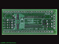
Now with the tweezers position the RS-232 transceiver chip on its place
observing the correct orientation for pin 1. In this case we used a SN65C3232.
When you have it in place, place the iron tip on pin 16 where we previously
applied some solder, let it cool.
Double check that all pins of the integrated circuit are on their respective
pads and the orientation is correct.
|
Now apply solder on the other pins, one useful technique is to solder first
the pin that is diagonally opposite from the pin we soldered first. Apply
just the amount of solder required to complete the connection to avoid
creating shorts between pins.
On this pass we also applied solder to connect the required jumpers for the
particular PICMicro we'll used in this board.
|
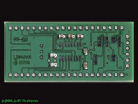
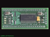
Now we turn to the top side. We do the same process applying some solder
on one of the pads for each component. When you have several components in
line, it works better to apply solder on the same side for each pad.
Also in some cases think which side will work best since after placing
a particular component it may get more difficult to place the iron tip
on the pads.
|
Using the same technique as on the bottom side and with the help of the
tweezers, place each component on its pads and apply the iron tip for each
on the pad where we previously applied solder.
Notice that we left some components such as the crystals for later.
|
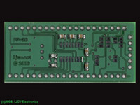
Verify that you have the right components in place, their polarity
(particularly for LEDs and tantalum capacitors), and that you like how
they are placed. Then apply solder on the other pads to complete soldering
each component to the board. As we did on the bottom side we can apply a
little bit more of solder on each opposing pad to make it more even.
We also use this pass to apply some solder on pin 28 for the PICMicro.
|
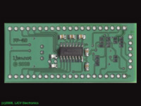
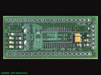
Like you did with the RS-232 transceiver in the bottom side, place the
PICMicro device on its pads, observing the correct orientation for pin 1.
When you have it in place, place the iron tip on pin 28 where we previously
applied some solder, let it cool.
Double check that all pins of the integrated circuit are on their respective
pads and the orientation is correct.
|
Now apply solder on the other pins, one useful technique is to solder first
the pin that is diagonally opposite from the pin we soldered first. Apply
just the amount of solder required to complete the connection to avoid
creating shorts between pins.
On this pass we also applied solder to one of the crystal pads for the
primary oscillator, we'll be using a surface mount package.
|
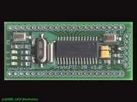
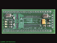
Solder the crystals, verify that all components are properly placed and
soldered and depending on your application solder the header connectors
for J1, J2A and J2B.
|
This picture shows a completed ProtoPIC28 with header connectors...
|
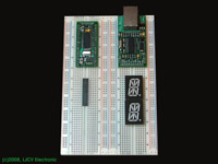
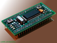
... and now installed on solderless breadboard ready for our next
PICMicro project.
|
